Abstract: Introducing the structure and working principle of common
battery thermal management systems for electric buses, providing a reference for the design of battery thermal management for electric buses.
Power battery performance has an important impact on the performance of electric buses, and the working temperature of the power battery is closely related to its performance but also affects the life and safety of the power battery. Therefore, the thermal management system of the power battery is also very important.
1 Several Forms Of Battery Thermal Management
The thermal management of a power battery includes cooling it at high temperatures and heating it at low temperatures.
1.1 Battery Cooling Methods
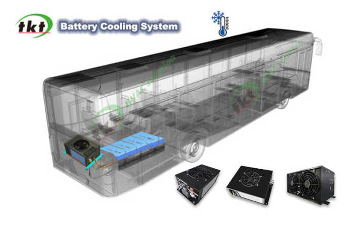
Common power battery cooling methods mainly include natural air cooling, forced air cooling, liquid cooling, and refrigerant direct cooling. Among them, forced air cooling is to directly introduce the air conditioning wind in the car, natural wind, or convection wind outside the car into the battery installation cabin to cool the battery pack. Liquid cooling is the use of air conditioning air or separate refrigeration equipment refrigerant cooling coolant cooling into the battery pack heat exchanger for heat transfer to the battery cells, to achieve the purpose of battery cooling. Refrigerant direct cooling is directly introduced into the heat exchanger inside the battery pack with refrigerant from separate refrigeration equipment to cool the battery by heat conduction to the electric cell. The comparison of different cooling methods is as follows:
1)The cooling performance of the natural air-cooling method depends on the external environment, does not take up space, has no need for control, has no energy consumption, low system cost, easy to realize, highest process reliability, low risk of water involvement.
2)The cooling performance of the forced air-cooling method is poor, the system volume is the largest, the risk of water involvement is high, but the weight is light, easy to control, low energy consumption, the system cost is relatively low, relatively easy to realize, the process reliability is high.
3) The liquid cooling method of cooling performance is better, the system volume is smaller, the control principle is mature, and the difficulty of medium relatively easy to realize, but the system weight of the method is heavier, high energy consumption, the highest system cost, process reliability is general, high risk of water-related. This is the industry's current commonly used cooling method.
4) The refrigerant direct cooling method of cooling performance is best, the system is smaller, lighter weight, lower energy consumption, and the system cost is medium, but the control principle is difficult to realize the difficulty of high process reliability, and high risk of water-related.
At present, the refrigerant direct cooling technology is not mature, is still in the research stage, and has not entered the engineering implementation stage. Although the heat transfer efficiency of the refrigerant direct cooling is high, but the refrigerant evaporates in the evaporation channel inside the battery pack when the temperature difference is large, and the battery temperature consistency is poor, thus affecting the battery's charging and discharging capacity. In addition, the bus has a large amount of power and a large number of battery packs, so the piping arrangement of direct refrigerant cooling is complicated and there is a risk of easy leakage.
1.2 Battery Heating Methods
Common Power Battery Heating Methods Are As Follows:
1) The integrated electric heating film inside the battery pack directly heats the battery cells. The effect of this heating method depends on the temperature of the external environment. When the ambient temperature is higher than 0 ℃, the electric heating film heating effect is better and does not take up space, has no control, no energy consumption, low system cost, easy to realize. Ambient temperature below 0 ℃, the electric heating film heating effect is poor, generally do not use this heating method.
2) in the battery thermal management water circulation system connected to the electric liquid heater on the antifreeze heating. The heating effect of this method is good, the system volume is small, only needs to occupy a part of the space, and the cost is relatively high, but the control principle is mature, the process reliability is high, relatively easy to realize, is currently the most commonly used battery heating method.
2 The Structure And Working Principle Of The Battery Thermal Management System
Whether it is winter or summer, the normal operating temperature of the battery is 25 ℃ ± 5 ℃, the winter needs to be heated through the battery thermal management equipment, heating the target water temperature of 25 ℃ ± 5 ℃. In summer, it needs to be cooled down by the battery thermal management equipment, and the target water temperature for cooling is also 25 ℃±5 ℃. The following is an introduction to the three kinds of buses that commonly use liquid-cooled (hot) battery thermal management systems, the three kinds of battery thermal management are heating and cooling systems, according to the use of purely electric bus and environmental temperature requirements, when the system needs to be cooled directly through the battery thermal management system heat exchanger on the antifreeze cooling; when the system needs to be heated, the battery thermal management of the water circulatory system connected to a series of PTC electro-liquid heater on the Antifreeze is heated.
2.1 Simple Unit Form
The simple unit includes a plate heat exchanger, water pump, fan, and PTC electric liquid heater.
1-plate heat exchanger. 2, 5-solenoid valve. 3, 4-water temperature sensor. 6-PTC. 7-fan. 8-controller. 9-pump
When the simple unit system receives the cooling signal, solenoid valve 2 opens, solenoid valve 5 closes, and the fan and water pump begin to work to extract cold air from the air conditioning duct through the induced draft tube. And the cold air passes through the plate heat exchanger inside the unit to complete the heat exchange with the antifreeze in the system, and then the antifreeze is sent into the heat exchanger inside the battery through the pump to reduce the temperature of the battery.
When the heating signal is received, the solenoid valve 2 closes and the solenoid valve 5 opens, the PTC electro-liquid heater inside the unit and the water pump start to work, heating the antifreeze inside the system. The same as the principle of the refrigeration cycle, through the antifreeze and the heat exchange of the heat exchanger plate inside the battery to achieve the purpose of warming up the battery.
In addition to heating and cooling, water-cooled units generally also have a self-circulation function, mainly to solve the problem of excessive temperature difference inside the battery. When receiving the self-circulation instruction from BMS, the PTC electro-liquid heater and fan stop working, the water pump operates normally, the antifreeze channel opens, and the water circuit operates in self-circulation to avoid excessive temperature difference inside the battery.
Simple units are simple in structure and relatively inexpensive. However, since there is no independent refrigeration system, cold air needs to be extracted from the compartment to reduce the antifreeze temperature, resulting in a smaller cooling capacity. In addition, the simple unit is also affected by the working condition of the
bus air conditioning system, and its use has limitations.
The cooling capacity of the simple unit is poor, and the cooling power is small (generally less than 2 kW), which is suitable for hybrid buses using slow-charging batteries with low battery charging and discharging multipliers.
2.2 Non-Independent Unit Form
Where: evaporator 1 for the air conditioning system evaporator, used to cool the cabin air. Evaporator 2 is a water-cooled unit evaporator, where the cooling water and refrigerant complete the heat exchange, cooling the battery by reducing the temperature of the antifreeze.
The two evaporator assemblies are in parallel, and they share a common set of compressor, condenser, drying bottle, and other components, and the flow of refrigerant in the two channels is controlled through solenoid valve 1 and solenoid valve 2 respectively, while the flow size of refrigerant in the two channels is adjusted by using expansion valve 1 and expansion valve 2 respectively.
When the battery needs to be warmed up, solenoid valve 2 closes, the water pump and PTC electro-liquid type heater start to work, and the antifreeze is heated by the PTC and then sent to the internal heat exchanger of the battery to heat the battery.
In self-circulation mode, the solenoid valve 2 closes, the PTC electro-liquid heater stops working, the water pump runs and the water circuit operates in self-circulation to avoid excessive temperature difference inside the battery.
Non-independent units do not require a separate cooling system, which can reduce the cost of thermal management equipment.
However, since the non-independent unit needs to divert part of the refrigerant from the air-conditioning system, it is bound to have a certain impact on the cooling effect in the passenger area, and it also increases the load of the air-conditioning system.
In addition, the excessively long air-conditioning high- and low-pressure pipelines from the air-conditioning system to the battery water-cooled units are not conducive to improving the energy-efficiency ratio of the air-conditioning system.
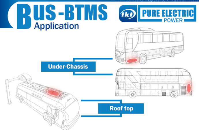
Finally, the condenser and evaporator assembly of the electric bus air conditioner is generally arranged on the roof, which limits the installation location of the battery thermal management equipment.
For example, when the battery is bottom-mounted, it is difficult to connect the high- and low-pressure pipelines between the battery water-cooling unit and the air conditioning system.
In fact, for bus companies, the vehicle air conditioner manufacturer and model of each model are not fixed, resulting in the more difficult matching of water-cooled units and air conditioners, which is also an important factor limiting the use of non-independent units.
In addition, the cooling power of non-independent units is larger, generally applicable to occasions above 6 kW.
Due to the conflict between the bus equipped with a non-independent unit battery thermal management system and the whole vehicle refrigeration needs, resulting in more complex control logic, applicable to the use of battery charging and discharging rate higher fast-charging batteries pure electric buses.
2.3 Independent Unit Form
The independent unit is equivalent to a small pure electric air conditioner, with an independent and complete cooling system.
Battery thermal management independent unit and ordinary air conditioning a big difference is that the structure of the evaporator is different.
The ordinary air conditioner evaporator is used for heat exchange between air conditioning refrigerant and air, but the internal evaporator of the independent unit is used for heat exchange between air conditioning refrigerant and antifreeze.
This special heat exchanger generally adopts the casing structure, and the heat exchange pipeline is divided into two layers, the refrigerant in the inner pipeline, the cooling water in the outer pipeline, and between the two layers of the pipeline, some fins are distributed to increase the heat exchange area.
The evaporator and condenser of the independent unit have two forms: one-piece design and
split design.
The independent unit needs a separate refrigeration system. When the system receives a refrigeration signal, the fan and pump start to work, and the refrigerant completes the heat exchange with the antifreeze in the system through the plate heat exchanger inside the unit, and then the antifreeze is sent into the heat exchanger inside the battery through the pump to reduce the temperature of the battery.
When the heating signal is received, the PTC electro-liquid heater and the water pump inside the unit will start to work to heat the antifreeze in the system, the same principle as the refrigeration cycle, through the heat exchange between the antifreeze and the heat exchanger plate inside the battery to achieve the purpose of warming up the battery.
Independent units can be designed with different power according to the need, matching the corresponding power of the compressor, evaporator, and other components.
So it can meet the demand of different refrigeration power, and the scope of use is more extensive.
Compared with the non-independent unit, the independent unit responds more quickly to the temperature change inside the battery, without having to consider the requirements of the passenger area on the air conditioning refrigeration performance, and the arrangement is also relatively flexible.
Compared with the non-independent unit system, the stand-alone unit has an additional set of compressors and condensers for separate refrigeration, which is more costly.
However, because it is an independent system, the control logic is simpler than that of a non-independent unit.
The cooling capacity of the independent unit system can be selected according to the needs, generally above 2 kW, and is suitable for hybrid buses and pure electric buses using fast-charging batteries with high battery charging and discharging multipliers.
3. Conclusion
The battery thermal management system, as an important part of the electric bus, effectively ensures the performance, safety, and life of the power battery. Therefore, in the actual design process, it is very important to fully understand the structure and working principle of the battery thermal system equipment.
If you still have questions or ideas about Battery Thermal Management System, please feel free to contact TKT. We are a professional manufacturer and supplier of BTMS systems. We can provide you with comprehensive services.


.jpg)
.jpg)